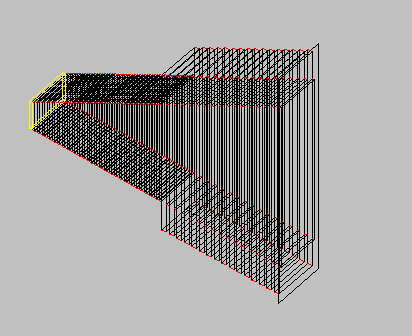
MODE MATCHING
Modelling Waveguide Components using Mode-Matching Techniques
BY P R Foster and Soe Min Tun
Introduction
The use of mode-matching techniques to analyse the performance of circular horns, particularly corrugated horns, has been well known for many years [1], [2], [3], [4]. The method is now mature and robust and horns are routinely manufactured by many companies using this technique. Recent advances in the theory have allowed the technique to be applied to more complex structures as varied as septum polarisers and small reflectors with splash-plate feeds. Comparison with measurement has shown the same excellent agreement as has been obtained with corrugated horns.
Theory
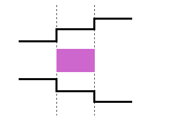
The essence of the mathematics is that the structure is subdivided into cylindrical slices. The modes which can propagate in each section, including in some cases evanescent modes, are set up and the complex amplitudes of the modes are matched across the boundary of the slice to the next slice, bearing in mind the boundary conditions (Figure 1). Clearly the mathematics will be written out rather differently for circular and rectangular components, since cylindrical coordinates are natural for circularly components and cartesian for rectangular components. The example below is for circular waveguide geometry and assumes that dielectrics are present.
FIGURE 1 Diagram showing
the division of the circular waveguide
into cylindrical sections which may be loaded with
dielectric (shown in purple).
The dashed lines show the boundaries between cylindrical sections across which the waveguide modes must be matched. |
 |
In order to solve for the complex amplitudes, it is necessary to evaluate eigen-modes of circular cross-sections loaded with dielectrics. The dielectric loading must be axially symmetric. Electric and magnetic field components within each loaded region are expressed in terms of Bessel functions. By matching tangential fields at the interfaces, a set of linear equations can be derived. Both the propagation coefficients and field distributions of eigen modes can then be obtained by solving the simultaneous equations [2]. The modes can either be transverse electric/magnetic or hybrid depending on the presence of dielectrics. Once the modal distributions are known coupling integrals between a pair of modes, one each from either sides, are evaluated at a junction between two cylindrical sections. The resulting complex coupling coefficients are cast into a matrix form and by performing algebraic matrix operations the multi-mode scattering matrix of the junction can be obtained. The overall scattering matrix of the structure can subsequently be obtained by cascading the scattering matrices. The desired complex amplitudes at the output of the structure are then obtained by multiplying the overall scattering matrix with the input excitation coefficients.
The method is easily extended to coaxial geometries and lossy dielectrics may be included. Since each 'slice' may contain a different geometry and/or dielectric, this program is ideally suited to the analysis of coaxial junctions. Many components and horns have been built based on designs from this type of software.
Because the modes have to be computed in different coordinate systems depending on the local structure, it is very difficult to write a general program to deal with absolutely every case and therefore a set of different programs applicable to different geometries has been written.
RECTGEN
RECTGEN extends the application of rectangular modes in waveguide to several rectangular waveguide segments. The structure to be analysed is modelled as a number of discrete rectangular or ridged waveguide segments supporting propagating as well as evanescent modes. Multiple waveguide aperture segments can coexist side by side. This flexibility extends the scope of the analysis software to include many waveguide network structures. In order to achieve an optimal run-time, modes within waveguide segments can be selected in a flexible manner and various symmetry conditions can be applied. For more details on the program, RECTGEN, click here.
Typical components are
- Symmetric and asymmetric rectangular waveguide tapers (may be overmoded) and step transformers.
- Multimode rectangular horn radiators.
- Rectangular corrugated horn radiators (radial corrugations also supported).
- Corrugated filters and polarisers.
- Multi-post and multiple iris waveguide bandpass filters.
- E and H plane rectangular waveguide couplers - Figure 4.
- Four horn monopulse radiator.
- Small waveguide networks and horn arrays - Figure 2.
- Single and double ridged waveguide tapers and step transformers.
- Evanescent mode filters.
- Septum polarisers (single or dual input ports) - Figure 2 and Figure 3.
AXIAL
AXIAL can be used to analyse combined circular and multiple coaxial structures with partial dielectric loading(optional) such as corrugated horns with ring loaded or V shape slots, axially corrugated horns, horns with dielectric rings, coaxial orthomode junctions (OMJs), multi-band coaxial feeds, dielectrically loaded horns and polyrod feeds and small splash-plate fed Cassegrainian antennas (see structure examples below). In principle, any circularly symmetric structure which can be decomposed into circular and coaxial regions can be modelled. The dominant TE11 mode excitation of either a circular or coaxial input A typical example is an axisymmetric Cassegrainian reflector with a splashplate feed [6], [7]. The exciting waveguide with its dielectric is modelled as a circular waveguide while the exterior of the waveguide and the reflector are modelled as a coaxial section (Figure 5). The great advantage of this type of analysis is that is allows an optimisation to be carried out which is much more accurate than the usual ray tracing. The result is an ability to design a high efficiency (65%) reflector with sidelobes of -22 dB and low spillover (<-40 dB) when the aperture is relatively small in wavelengths. Examples up to 12 wavelengths in diameter have been designed and manufactured and are now in production.
For more details on the program, AXIAL, click here.
RTCC
RTCC deals with mixed rectangular and circular waveguide. A dominant mode excitation is assumed at the input waveguide (TE10 for rectangular and TE11 for circular). Structures which can be analysed (see below) include
- small rectangular corrugated horns
- mixed waveguide transitions
- corrugated polarisers with circular ports
- filters with circular irises
Figure 6, Figure 7 and Figure 8 show results from this program. An optimiser program, OPTRTCC, can be used to optimise dimensions for a specified RF performance. An example of a polariser from EASAT Antennas Limited is shown in Figure 9.
For more information on the programs, RTCC and OPTRTCC, click here.
Platforms
These programs are available on several platforms.
References
- Wexler, A, Solution of Waveguide Discontinuities by Modal Analysis, IEEE Trans on Microwave Theory and Tech, MTT-15,1967, p503-51
- James, G. L., Analysis and Design of TE11 to HE11 Corrugated Cylindrical Waveguide Mode Converters, IEEE Trans. on Microwave Theory and Techniques, Vol. MTT-29, No. 10, Oct. 81, pp. 1059-1066
- Kuhn, E and Hombach, V, Computer Aided Analysis of Corrugated Horns with Axial or Ring-loaded Slots, ICAP-83, IEE Int Conf on Ant and Prop, IEE Conf Publ No 127, 1983, p127-131
- Patzelt, H and Arndt, FR, Double-plane Steps in Rectangular Waveguides and their Application to Transformers, Irises and Filters, Trans IEEE on Microwave Theory and Tech, MTT-30, No 5, 1982, p771-776
- Alessandri F, Bartolucci, G and Sorrentino A, Admittance Matrix Formulation of Waveguide Discontinuity Problems: Computer Aided Design of Branch-line Couplers, Trans IEEE on Microwave Theory and Tech, MTT-36, No 2, 1988, p394-403
- S. M. Tun, Mode Matching Analysis of Combined Circular and Coaxial Structures Loaded with Dielectrics. Int. Conf. on Computation in Electromagnetics 91, Nov. 1991, IEE Conf. Publ. No. 350, pp 230-233.
- S. M. Tun & P. R. Foster, Mode Matching Analysis of Small Cassegrainian Reflector Antennas, ICAP 93, April 1993, IEE Conf. Publ. No. 370, pp 627-630.
- Fontecha, J.L., and Cagigal, C, Transition Rectangular to Circular Waveguide by means of Rectangular Guides, IEE Conf on Computational Electromagnetics, CEM-91, IEE Conf Publ No 350p379-381
- Narasimhan, M.S. and Rao, B.V, Radiation Characteristics of Corrugated E-plane Sectorial Horns, IEEE Trans on Ant and Prop, AP-21, No 3, 1973, p320-32
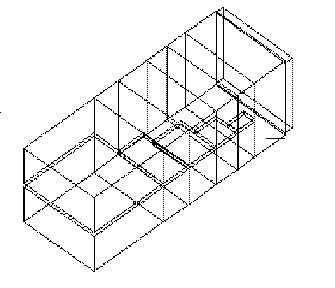 FIGURE 2 Geometry of Septum Polariser from RECTGEN |
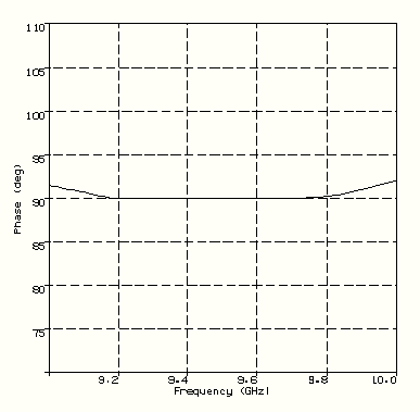 FIGURE 3 Differential Phase Performance of a Dual Port Septum Polariser |
FIGURE 4
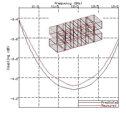
Predicted (RECTGEN) and Measured Coupling Response of a Waveguide Hybrid Coupler. Measured results from [5].
FIGURE 5
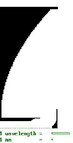
Cross-section of a Cassegrainian Reflector with splashplate feed (AXIAL). Graphics captured from WINDOWS
FIGURE 6
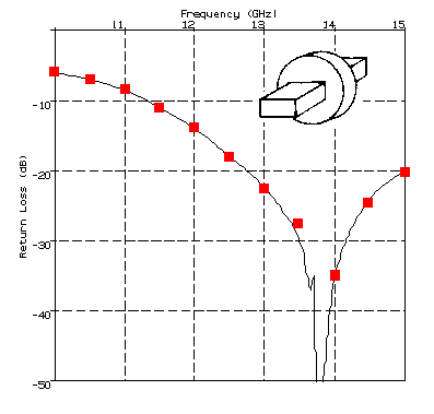
Return Loss from a disc cavity fed by rectangular waveguides.
Solid Line -measured results from [8]. Red squares predicted by RTCC
FIGURE 8 Computed radiation patterns for an E-plane sectoral horn (RTCC). Green - E-plane; Blue - H-plane: Red - D-plane; Purple - Crosspolarisation See Figure 7 for geometry. Measured results of [9] are indistinguishable from these. |
FIGURE 9
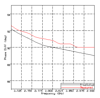
Predicted and Measured Performance of a Polariser in Rectangular Waveguide with two opposed walls corrugated
