CORRUG
Analysis of Circularly Symmetric Waveguide and Horn
Structures
Applications Of The Program CORRUG
Analysis of Circularly Symmetric Waveguide and Horn Structures
Applications Of The Program CORRUG
The program suite CORRUG can be used to analyse circularly symmetric waveguide and horn structures such as corrugated horns, dual-mode horns, smooth walled horns, step transformers, tapers, etc.
Modelling Methods Used By CORRUG
The mathematical basis of the analysis program exploits a modal matching technique. The structure to be analysed must be modelled as a number of discrete cylindrical segments supporting propagating as well as evanescent TE and TM circular waveguide modes. The modal matching employs a scattering matrix approach to determine the complex coefficients of the modes at the aperture of the horn. The far-field radiation patterns are then obtained by summing individual radiation patterns of TE and TM modes at the aperture, weighted by the complex mode coefficients.
Although the dominant TE11 mode excitation is the most likely to be used at the component input and is the default excitation, the user may specify the amplitude and phase of a number of higher order modes as input waveguide modes.
Program Contents
The program suite CORRUG consists of a pre and post processor program PREPCOR and an analysis program CORRUG. Input data files for CORRUG can be prepared interactively using PREPCOR which incorporates many screen editing facilities. A waveguide/horn profile generator is also built into PREPCOR to enable repetitive generation of complex structures such as corrugated horns by simply altering a few key parameters. The profile of the resultant structure can be viewed and modified interactively prior to analysis. The computed radiation patterns of the horn can also be displayed on the computer screen and each radiation point can be examined.
A DXF file of the component profile can also be generated.
CORRUG was developed by Dr.S.M.Tun of S.M.T. Consultancies Ltd.
Examples
Figure 1 below shows the geometry of a circular corrugated horn and Figure 2 shows the radiation patterns at 12 GHz.
Figure 3 below shows the geometry of a dual mode Potter horn and Figure 4 shows the radiation patterns at 17 GHz.
A horn for SMILES at 600 GHz, designed and built by Thomas Keating Limited had measured patterns very close to prediction (Figure 5)
Platforms
CORRUG is available on these platforms.
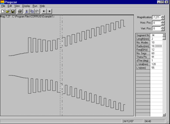
Figure 1: Screen dump of geometry of circular corrugated horn from CORRUG. The tabulated parameters on the right hand side refer to the section of the horn outlined with dashed vertical lines.
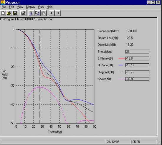
Figure 2: Principal plane radiation patterns of the circular horn of Figure 1 at 12 GHz
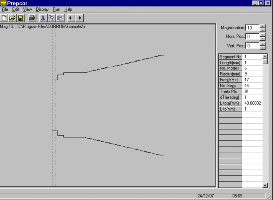
Figure 3: Screen dump of a dual mode Potter horn. The tabulated parameters on the right hand side refer to the section of the horn outlined with dashed vertical lines.
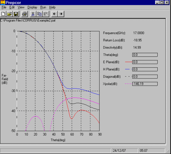
Figure 4: Principal plane radiation patterns of the horn of Figure 3 at 17 GHz
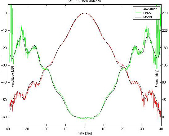 FIGURE 5a Measured radiation patterns from SMILES horn at 600 GHz (Thomas Keating Limited) |
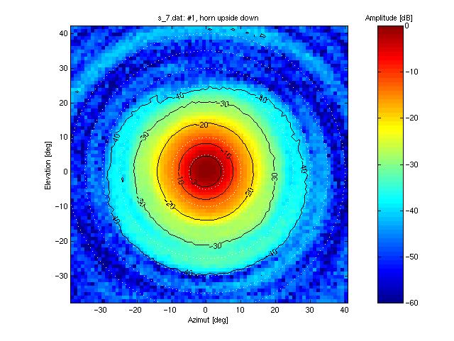 FIGURE 5b Measured radiation patterns(amplitude) from SMILES horn at 600 GHz (Thomas Keating Limited) |