RTCC
Analysis of Mixed Rectangular and Circular Structures
Applications Of RTCC
The program suite RTCC can be used to analyse a variety of mixed rectangular and circular waveguide structures (Figure 1) including
- small rectangular corrugated horns - Figure 4 and Figure 5
- mixed waveguide transitions - Figure 2
- disc cavity - Figure 3
- corrugated polarisers with circular ports
- circular horns with integral transitions to rectangular waveguide - Figure 6
- Waveguide Filters - Figure 7
A dominant mode excitation is assumed at the input waveguide (TE10 for rectangular and TE11 for circular). An additional program, OPTRTCC can be used to optimise the geometry for a specified performance.
FIGURE 1: Sample Geometries for RTCC
Modelling Method Used By RTCC
The mathematical basis of the analysis program exploits a modal matching technique. The structure to be analysed is modelled as a number of discrete rectangular and circular segments supporting propagating as well as evanescent modes. Farfield patterns are obtained from the final aperture which may be either rectangular or circular are obtained by applying the Kirchhoff-Huygens field integration scheme.
Examples
Two examples of corrugated horns designed using RTCC are given. OPTRTCC was also used.
Program Contents
The program suite RTCC consists of a pre and post-processor program, PREPRTCC, and an analysis program, RTCC.
Input files for RTCC can be prepared interactively using PREPRTCC which incorporates a full range of screen editing functions. The data processing section also supports a programmable mouse such as a Logitech mouse.
RTCC was developed by Dr.S.M.Tun of S.M.T. Consultancies Ltd.
An optimisation program, OPTRTCC, is available for RTCC.
Platforms
RTCC is available on these platforms.
References
- Narasimhan, M.S. and Rao, B.V, Radiation Characteristics of Corrugated E-plane Sectorial Horns, IEEE Trans on Ant and Prop, AP-21, No 3, 1973, p320-32
- S M Tun and P R Foster, ‘Computer Optimised Wideband Dual-mode Horn’, Electronics Letters, Vol 38, no 15, 18th July 2002, p768-9
FIGURE 2: Waveguide Filter Geometry and Results from RTCC and OPTRTCC.
FIGURE 3: Return Loss from a disc cavity fed by rectangular waveguides. Solid Line -measured results from [8]. Red squares predicted by RTCC
FIGURE 4: E Plane Corrugated Horn Geometry from Ref[1].
FIGURE 5: Measured E Plane cut(dashed line) from Ref[1] against RTCC prediction.
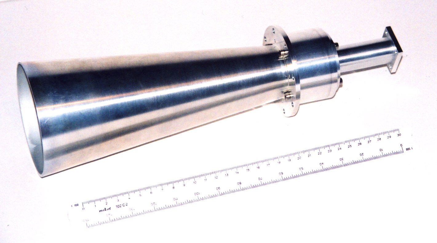
FIGURE 6: Results for multi-step Potter Horn optimised using OPTRTCC and predicted using RTCC Ref[2].
FIGURE 7: Waveguide Filter Geometry and Results from RTCC and OPTRTCC.