Wide Band Corrugated Horns at C Band
Two design examples of corrugated horns operating over the frequency bands 3.6-4.2 GHz(Rx) and 5.925-6.425 GHz(Tx) are given below. The results for these circularly symmetric horns have been computed using an accurate mode matching program(RTCC). In both cases good cross-polarisation characteristics have been obtained without the use of ring loaded slots. In the matching sections of the horns, variable width slots are used to control un-wantd mode conversion and to achieve good return loss.
1. A High Performance Horn
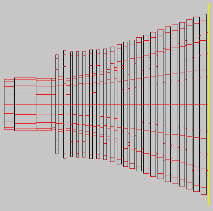
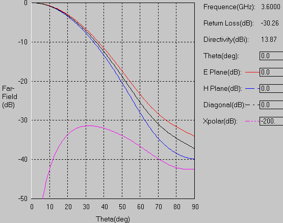
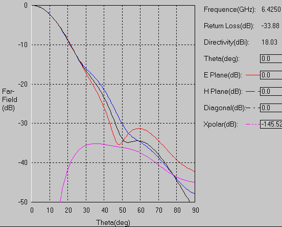
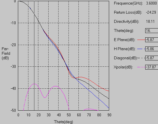
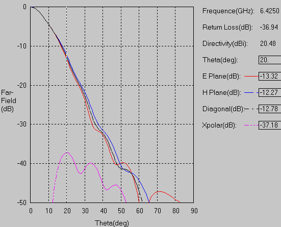
A C band corrugated horn(Figure 1) was required to perform well over both the receive and transmit bands. The horn aperture diameter at the lowest frequency was approximately 4 wavelengths. The worst case cross-polar level was found to better than -37 dB(relative to copolar peak) in both the transmit and receive bands. Far field radiation patterns predicted using an accurate mode matching program are given in Figure2 (3.6GHz) and Figure3 (6.425GHz) at band edge frequencies only for brevity.
2. A Compact Horn
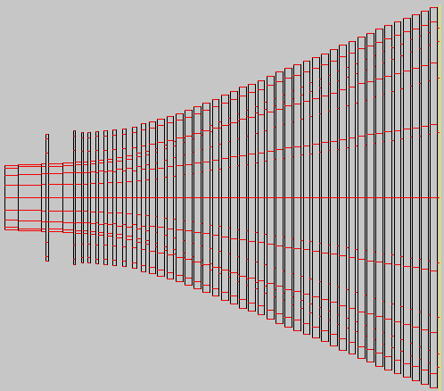
A compact C band corrugated horn(Figure 4) was designed to yield a better cross-polarisation performance in the transmit band. The horn aperture diameter at the lowest frequency was approximately 2 wavelengths. The worst case cross-polar level was found to better than -35 dB(relative to copolar peak) in the transmit band and -30 dB in the receive band. Such a small horn is most suited for VSAT applications. The design of the horn was accomplished using a fully automatic optimizer(OPTRTCC) in the final phase of the design. Far field radiation patterns predicted using an accurate mode matching program are given in Figure5(3.6GHz) and Figure6 (6.425GHz) at band edge frequencies only for brevity.
