Broadband Ku Band Horn
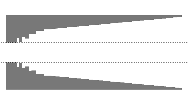
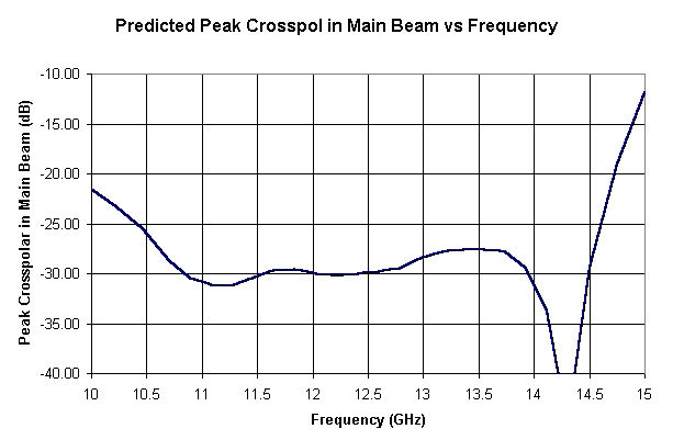
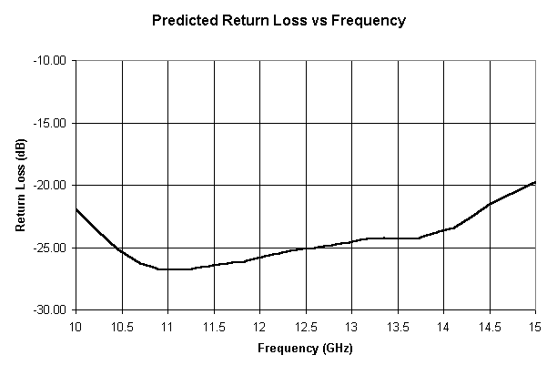
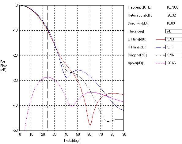
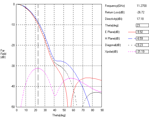
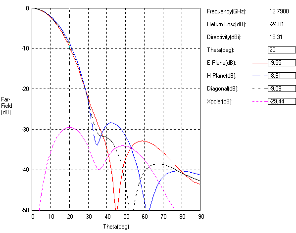
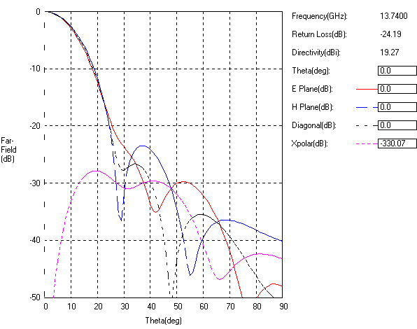
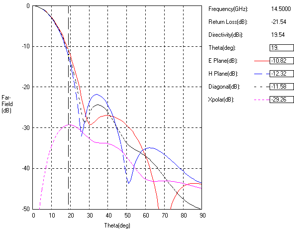
A smooth-walled multi-mode horn(Figure 1) with a multi-step mode generator was optimised using a modal matching program(optrtcc). The design aim was to achieve lowest peak crosspolar in the main beam from 10.7 GHz to 14.5 GHz while retaining the conical flare. A similar horn had been designed for J band in the reference [1] given below. Predicted peak cross-polar level vs frequency plot is shown below in Figure 2. Like wise The return loss plot is shown in Figure 3. Predicted far-field patterns in Rx at 10.7 GHz, 11.3 GHz and 12.8 GHz are given in Figure 4, Figure 5, Figure 6. Predicted far-field patterns in Tx at 13.7 GHz and 14.5 GHz are given in Figure 7, Figure 8. Note that the sidelobe levels are generally higher in Tx.
Reference 1: Tun,S.M, .Foster, P.R. , 'Computer optimised wideband dual-mode horn', Electronics Letters, Vol.38, No.15, July 2002, pp. 768-769.